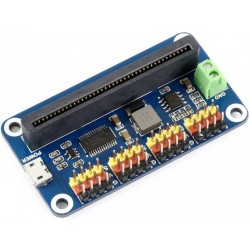


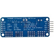
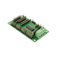
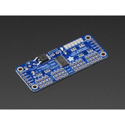
Com este módulo poderá controlar até 16 servos com apenas dois pinos do microcontrolador. O chip PCA9685 recebe as ordens por i2c do microcontrolador e garante depois o funcionamento continuo de cada servo até nova instrução, libertando assim o microcontrolador para outras tarefas.
DESCRIÇÃO EM PORTUGUÊS BREVEMENTE DISPONÍVEL
Se tiver alguma dúvida neste produto não hesite em contactar-nos.
*Atenção: as imagens são meramente ilustrativas.
With this pwm and servo driver breakout, you can control 16 free-running PWM outputs with just two pins! Need to run more than 16 PWM outputs? No problem. Chain together up to 62 of these beauties for up to an outstanding 992 PWM outputs.
Unlike the TLC5940 family, with this board you do not need to continuously send it signal tying up your microcontroller, its completely free running!
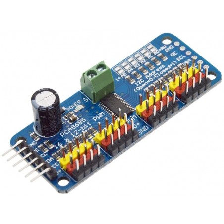
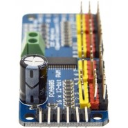
Note: Servo plugs are slightly wider than 0.1" so you can only stack 4 next to each other on 0.1" header "Chain-able" design A spot to place a big capacitor on the V+ line (in case you need it) 220 ohm series resistors on all the output lines to protect them, and to make driving LEDs trivial Solder jumpers for the 6 address select pins i2c-controlled PWM driver with a built in clock. Unlike the TLC5940 family, you do not need to continuously send it signal tying up your microcontroller, its completely free running! It is 5V compliant, which means you can control it from a 3.3V microcontroller and still safely drive up to 6V outputs (this is good for when you want to control white or blue LEDs with 3.4+ forward voltages)
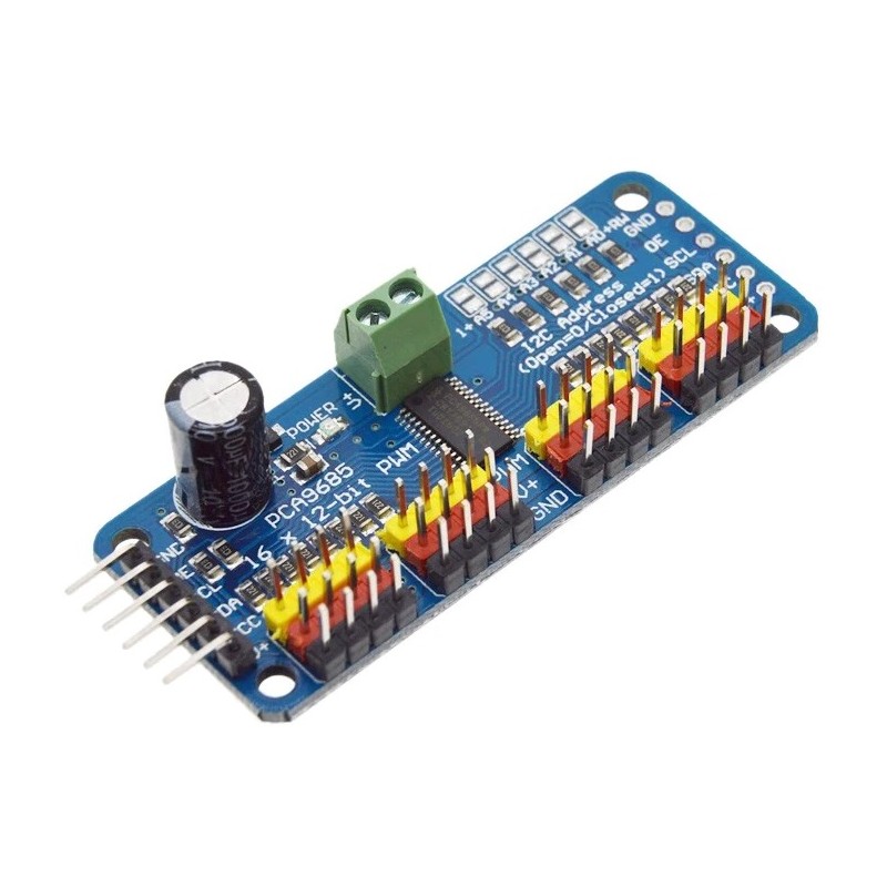
VCC pin is only for the chip power supply, if you want to connect the servo or LED lights, use the V + pin power supply, V + pin supports 3.3 ~ 6V power supply (chip safe voltage 5V). It is recommended to connect the external power supply via the power supply terminal.
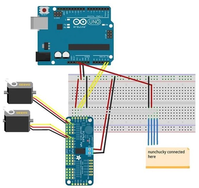
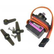
Power supply: Most of the servo design voltage is 5 ~ 6V, especially in a number of steering gear at the same time running, with the need for high-power power supply. If you are directly using the Arduino 5V pin to power the servo directly, there are some unpredictable problems, so we recommend that you have a suitable external power supply for the drive board.
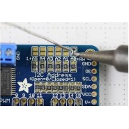
Each drive board of the cascade needs to have a unique access address. The initial I2C address of each driver board is 0x40, you can modify the upper right corner of the jumper I2C address. Connect a jumper with solder to indicate a binary number "1".
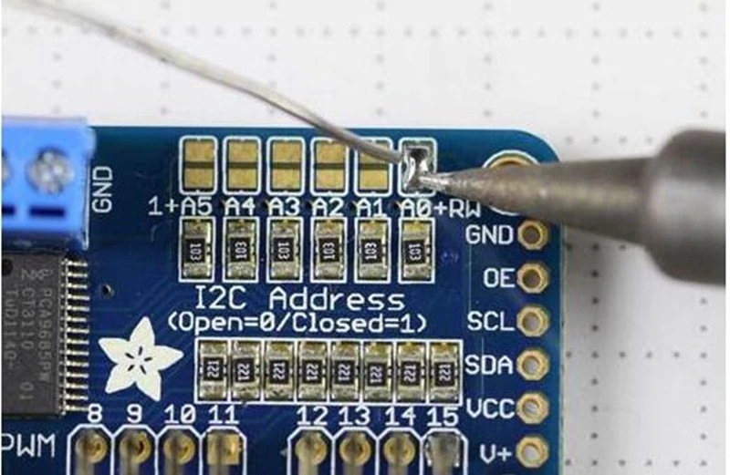
Board 0: Address = 0x40
Offset = binary 00000 (default)
Board 1: Address = 0x41 Offset = binary 00001 (as shown above, connected to A0)
Board 2: Address = 0x42 Offset = binary 00010 (connect to A1)
Board 3: Address = 0x43 Offset = binary 00011 (connect A0 and A1)
Board 4: Address = 0x44 Offset = binary 00100 (connect to A2)
And so on. . .
Code example:
#include
#include
Adafruit_PWMServoDriver pwm1 = Adafruit_PWMServoDriver (0 × 40);
Adafruit_PWMServoDriver pwm2 = Adafruit_PWMServoDriver (0x41);
Void setup () {
Serial.begin (9600);
Serial.println ( "16 channel PWM test! ");
Pwm1.begin ();
Pwm1.setPWMFreq (1600); // This is the maximum PWM frequency
Pwm2.begin ();
Pwm2.setPWMFreq (1600); // This is the maximum PWM frequency
// ( ... )
}

Produtos Associados
Com este módulo poderá controlar até 16 servos com apenas dois pinos do microcontrolador. O chip PCA9685 recebe as ordens por i2c do microcontrolador e garante depois o funcionamento continuo de cada servo até nova instrução, libertando assim o microcontrolador para outras tarefas.