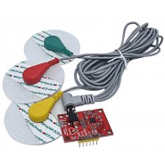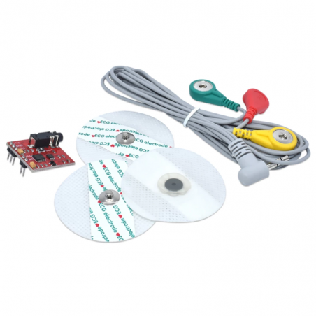


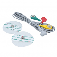
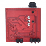

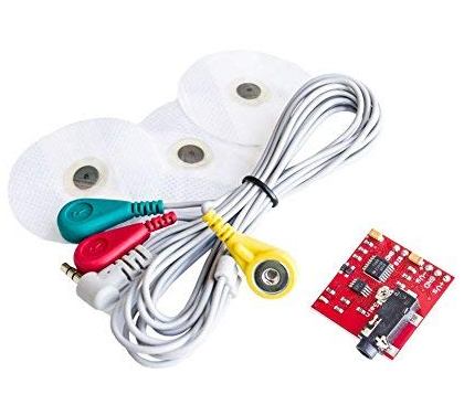
Este Kit de sensor muscular com cabo e eletrodos medirá a atividade elétrica filtrada e retificada de um músculo, emitindo 0 até XVolts dependendo da quantidade de atividade no músculo selecionado
Se tiver alguma dúvida neste produto não hesite em contactar-nos.
*Atenção: as imagens são meramente ilustrativas.
Electromyography (EMG) is a medical procedure that evaluates the health conditions of muscles and nerve cells. These cells transmit electrical signals that cause muscles to contract or relax. EMG is used to read these signals and plot them as numbers or graphs.
Typically, EMG is performed by doctors as one part of a diagnostic tool that can detect a potential muscle or nerve disorder. However, EMG sensors are also used in muscle-controlled electronic applications — such as for controlling a servo motor or robotic arm by using muscle-like movements.
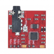
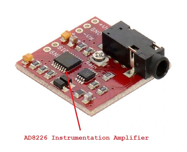
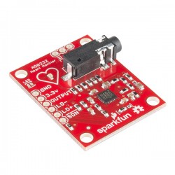
In this project, we’ll use an AD8226-based EMG sensor to plot an EMG graph with the help of Arduino. AD8226 is an instrumentation amplifier that’s widely used to design sensors. It provides gains from 1 to 1000. It’s also widely used in medical instrumentations, bridge amplifiers, industrial process control, and portable data-acquisition systems.
Here, we’ll learn how to interface an AD8226-based EMG sensor with Arduino UNO and plot the electrical activities of a muscle group on Arduino UNO. The sensor can be used to measure the activation of any group of muscles, including biceps, quads, calves, etc.
Although the sensor is not an industry-grade EMG device, it is effective for measuring and monitoring muscle activation. It can be used for robotics, prosthetics, and a variety of control applications.
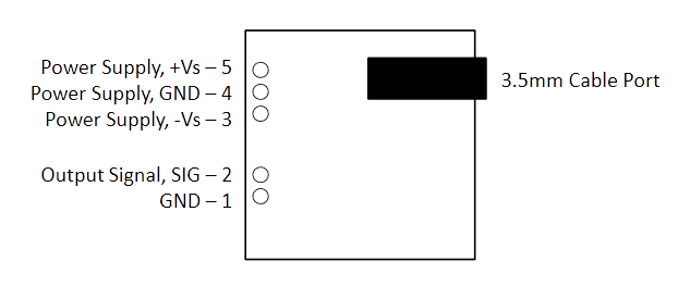
The sensor board has this pin configuration:
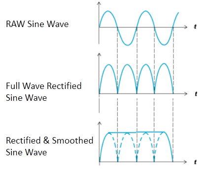
The sensor is ideal for use with microcontrollers. Unlike industry-grade medical sensors, however, it does not output raw EMG signals. Rather, an amplified, rectified, and smooth signal is delivered that can be read at Arduino’s analog input pin (or any other microcontroller).
The board is powered by DC voltage that ranges from +/-3.5 to +/-18V. The output signal voltage can range to 0V. The sensor’s gain can be changed using an onboard potentiometer, which can be adjusted between 0.002 for 0.01Ω to 20,700 for 100KΩ on the pot. The output differential signal can vary from 0mV to the supply voltage/gain.

The sensor board uses an AD8226 instrumentation amplifier. It requires only one external resistor to set the gain from 1 to 1000. The amplifier operates on supplies, ranging between +/-1.35 to +/-18V (for dual supplies) and 2.2 to 36V (for a single supply).
It’s can also handle voltages beyond its rail-to-rail voltage. For example, even with a 5V supply, the IC can withstand up to +/-35V.
The AD8226 is a small form factor, multichannel, low-cost, and low-power amplifier.
The sensor board has two sets of pins:
To begin, you’ll need the two 9V batteries. Connect the positive terminal of one battery to the +VS pin. Then, connect the negative terminal of that same battery with the positive terminal of the second battery, joining it to the GND pin in the 3-pin header.
Next, connect the negative terminal of that second battery to the -Vs pin. This provides the +/-9V dual-supply to the sensor.
To interface with Arduino, connect the GND pin in the 2-pin header to any of the two ground pins on Arduino UNO. Lastly, connect the signal pin to any analog input pin, such as A1.
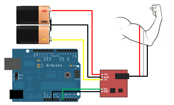
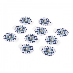
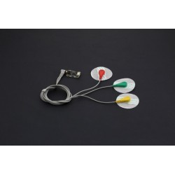
Ensure the 3-lead cable that’s equipped with a 3.5mm jack, is connected to the sensor board. The EMG/ECG electrodes can, then, be attached to the cable.
Pick a muscle group to monitor, such as a bicep or calf. Place one electrode in the middle of this muscle group and attach the red cable’s snap connector to this electrode. Next, place a second electrode at one end of this muscle group, attaching the green cable’s snap connector to this electrode.
Then, place the third electrode on a bony or non-muscular part of the body that’s near the same muscle group. Attach the yellow cable’s snap connector to this electrode.
int EMGPin = A1;

int EMGVal = 0;
void setup() {

Serial.begin(115200);

}
void loop() {

EMGVal = analogRead(EMGPin);

Serial.println(EMGVal);

}
The EMG signals can range from 50u to 30 mV. The AD8266 sensor offers a gain of up to 1000, which can amplify the EMG potentials to the mV level. The “read” EMG signals are amplified, rectified, and smoothed by the AD8226 instrumentation amplifier.
When the electrodes are properly placed on a muscle group, their contraction and relaxation produce EMG potentials. These potentials are picked up by the sensor and amplified to a measurable range. The sensor board’s gain can be adjusted by using an onboard potentiometer.
The output signal from the sensor board is read via Arduino’s input pin. As the output signal from the sensor board is rectified (and in mV range), Arduino can easily read it. Arduino is programmed to read the analog input at its A1 pin and print the readings to the serial port.
These EMG readings can be set and monitored as numbers, ranging from 0 to 1023, on Arduino IDE’s serial monitor or as a graph on its serial plotter.

Produtos Associados

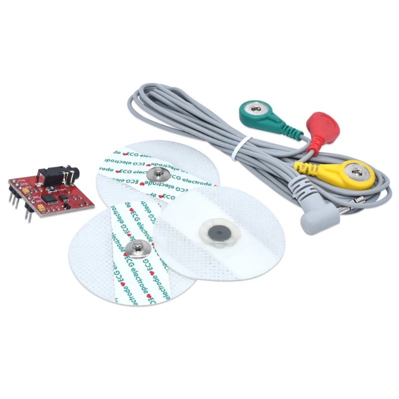
Este Kit de sensor muscular com cabo e eletrodos medirá a atividade elétrica filtrada e retificada de um músculo, emitindo 0 até XVolts dependendo da quantidade de atividade no músculo selecionado