

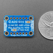
Para microcontroladores sem conversor analógico-digital ou quando quer um ADC de alta precisão, o ADS1015 fornece precisão de 12-bit em 3300 amostras/segundo por I2C. Ainda inclui um amplificador de ganho programável, até x16, para ajudar a impulsionar os mais pequenos sinais single / diferenciais.
DESCRIÇÃO EM PORTUGUÊS BREVEMENTE DISPONÍVEL
Se tiver alguma dúvida neste produto não hesite em contactar-nos.
*Atenção: as imagens são meramente ilustrativas.
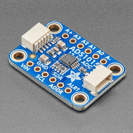
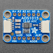
For microcontrollers without an analog-to-digital converter or when you want a higher-precision ADC, the ADS1015 provides 12-bit precision at 3300 samples/second over I2C. The chip can be configured as 4 single-ended input channels, or two differential channels. As a nice bonus, it even includes a programmable gain amplifier, up to x16, to help boost up smaller single/differential signals to the full range. We like this ADC because it can run from 2V to 5V power/logic, can measure a large range of signals and its super easy to use. It is a great general purpose 12 bit converter.
The chip's fairly small so it comes on a breakout board with ferrites to keep the AVDD and AGND quiet. Interfacing is done via I2C. The address can be changed to one of four options (see the datasheet table 5) so you can have up to 4 ADS1015's connected on a single 2-wire I2C bus for 16 single ended inputs.
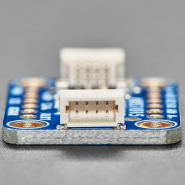
To get you going fast, we spun up a custom-made PCB in the STEMMA QT form factor, making it easy to interface with. The STEMMA QT connectors on either side are compatible with the SparkFun Qwiic I2C connectors. This allows you to make solderless connections between your development board and the ADS1015 or to chain it with a wide range of other sensors and accessories using a compatible cable.
QT Cable is not included, but we have a variety in the shop.
We have example code for both the Raspberry Pi, Arduino and CircuitPython. Simply connect GND to ground, VDD to your logic power supply, and SCL/SDA to your microcontroller's I2C port and run the example code to start reading data.


The default I2C address is 0x48.
The ADC on the breakout requires between 2V to 5V power/logic, and can be easily used with most microcontrollers from an Arduino to a Feather or something else.
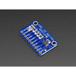
On the back of the board is one address jumper, labeled A0, below the I2C Addr label on the board silk. This jumper allows you to chain up to 2 of these boards on the same pair of I2C clock and data pins. To do so, you solder the jumper "closed" by connecting the two pads.
The default I2C address is 0x48. The other address options can be calculated by “adding” the A0 to the base of 0x48.
A0 sets the lowest bit with a value of 1. The final address is 0x48 + A0 which would be 0x49.
If A0 is soldered closed, the address is 0x48 + 1 = 0x49
The table below shows all possible addresses, and whether the pin(s) should be high (closed) or low (open).

The ADS11x5 chips have a base 7-bit I2C address of 0x48 (1001000) and a clever addressing scheme that allows four different addresses using just one address pin (named ADDR for ADdRess). To program the address, connect the address pin as follows:


Produtos Associados

Para microcontroladores sem conversor analógico-digital ou quando quer um ADC de alta precisão, o ADS1015 fornece precisão de 12-bit em 3300 amostras/segundo por I2C. Ainda inclui um amplificador de ganho programável, até x16, para ajudar a impulsionar os mais pequenos sinais single / diferenciais.