O RoboSpine realiza a varredura de até 8x SRF01, 2x sensores de alcance IR, 1x CMPS11, 1x sensor térmico TPA81 e o MD25 / MD49 (parte do sistema de acionamento / RD03 RD02) encoders, tensão da bateria etc.
DESCRIÇÃO EM PORTUGUÊS BREVEMENTE DISPONÍVEL
Se tiver alguma dúvida neste produto não hesite em contactar-nos
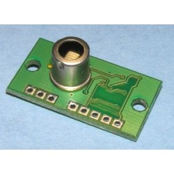
RoboSpine - Robot interface module
Technical Documentation

Overview
RoboSpine is a module to connect your controller to the various sensors on your robot via a simple serial (UART) interface. It can connect to a local controller such as an Arduino or RPi, or via a Bluetooth module to your PC. It can gather the data from up to 8 SRF01's, 2 Sharp IR rangers, TPA81 thermal sensor, CMPS11 and other various other I2C modules. Motor data is passed back to the MD25 motor controller. It features the same serial to I2C commands that are used in our USB-I2C modules, so you can connect any I2C device to the RoboSpine. It also has a SCAN command. This allows you to send motor data to the robot and responds with a 60 byte data stream containing all your sensor data. RoboSpine also has a set of 8 I2C hooks. These allow you to include data from your own I2C devices in the data stream, keeping everything working at full speed.
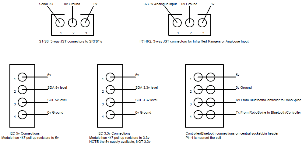
Connections
|
TPA81 directly plugs in, or spare I2C connection |
|||
|
S1 - S4 |
|
S5 - S8 4 x SRF01's (center) Bluetooth or controller connector |
|
| IR1 - IR2 Direct connection to Sharp IR rangers or analogue inputs. |
3.3v Level I2C with 5v power. |
||
| 5v Level I2C with 5v power | 12vdc module power from battery | ||
Boot Loader Mode
The RoboSpine has a built in boot loader that may be used for uploading new versions of the firmware. New firmware is downloaded over the same Bluetooth link that you use to control it, so make sure that is working before you start. We use Microchip's high speed PIC18 bootloader AN1310, which you will need to download and install from Microchip. To get into the bootloader mode, press and hold the RoboSpine push switch while switching on. A red LED will light up indicating you are in the bootloader. Now run the AN1310 application. Go to Program->Settings and select the correct comm port and make sure the bootloader speed is 9600 (Application speed does not matter). Now press the Red square symbol (bootloader mode) and wait a few seconds for it to connect to the RoboSpine. Next go to file open and select the version of the firmware you want to load into the RoboSpine, and press Write (the Red arrow on a black square). It will first erase the existing program (which normally fails because it times out - press it again) then program the new version. When finished (about 4 seconds to do the programming) cycle power on the RoboSpine and you should have the green LED on.
RoboSpine firmware V1 (original)
RoboSpine firmware V2 (includes MD49 support)
LEDs - There are three Leds on the module.
Green Led - This indicates power is on and the RoboSpine firmware is running.
Yellow Led - Flashes during communications with your Controller or Bluetooth.
Red Led - Indicates boot loader mode
Flashing Red Led - An error is detected on the I2C lines (checked on power-up only).
Power
The RoboSpine module is powered from 12v and can be connected to the same 12v SLA battery that powers your robot. There is an efficient switching power supply on the module delivering 5v for all the sensors attached to it. The RoboSpine processor is running from 3.3v and there is a small 3.3v regulator on the module dropping the 5v down to 3.3v. This is just for the processor and is not available on any of the connectors. Finally the TPA81 has its own linear 5v regulator to provide a quiet supply. The 12v supply to the module is brought in on the 3-way screw terminal and the connections are clearly marked on the PCB. If using the RD03 (24v system) you will need to provide a 12v supply, we used a 7812 regulator to drop the 24v down to 12v.
Serial Communications
The RoboSpine module communicates with the Controller/Bluetooth module at 38400 baud, 1 stop, no parity. Because the Bluetooth module defaults to 9600 baud, the RoboSpine will automatically send the command to increase it to 38400 baud at power on (AT+BAUD6). If you are using your own controller you can ignore this initial command.
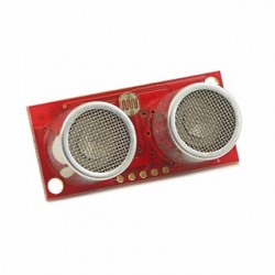
SRF01's
The RoboSpine module uses 8 separate serial lines for the SRF01's, this means you do not need to change any SRF01 addresses, they should be left at the factory default address of 1.
TPA81
If you use a TPA81, this will connect directly into the 5-way/3-way sockets on the PCB.
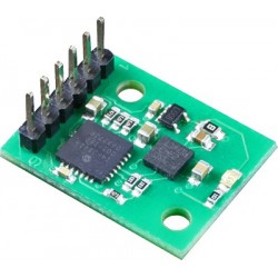
CMPS11
The CMPS11 communicates over a 3.3v I2C bus and requires 3.6-5v. It should therefore be connected to one of the two I2C-3.3v pin headers.
MD25/RD02
The MD25 requires 5v level I2C signals and must be connected to one of the two I2C-5v connectors. Do not connect the 5v supply between the two modules. If you do the module with the slightly higher voltage will supply all the current, and if that's the MD25 its linear regulator will get too hot. As both RoboSpine and the MD25 have their own 5v supplies you should leave the 5v unconnected. You should just connect the 0v ground, SCL and SDA lines.
MD49/RD03
The MD49 uses a serial interface and connects to the RoboSpine module on the IR1 and IR2 connectors. This means the analogue inputs are not available when using the MD49. IR1 is the Tx to MD49, IR2 is Rx from MD49. The connection cable is easy to make using one 3-way JST cable and one 3-way JST to JST cable. Cut the 3-way JST to JST in half and then remove the red wires from both and the black wire from one of them. You now have a cable with black and yellow wires and one with just a yellow wire. Solder them to the 3-way JST cable like this:

RoboSpine Command Set
| Command | Value | Description |
| I2C_SGL | 0x53 | Read/Write single byte for non-registered devices, such as the Philips PCF8574 I/O chip. |
| I2C_AD0 | 0x54 | Read/Write multiple bytes for devices without internal address or where address does not require resetting. |
| I2C_AD1 | 0x55 | Read/Write 1 byte addressed devices (the majority of devices will use this one) |
| I2C_AD2 | 0x56 | Read/Write 2 byte addressed devices, eeproms from 32kbit (4kx8) and up. |
| I2C_HOOK | 0x57 | Used to setup I2C data hooks. |
| ROBOSPINE | 0x5A | Used to get versions and scanning |
The RoboSpine always operates as an I2C bus master. It implements a set of 6 commands. The first 4 commands 0x53 to 0x56 are used to access any I2C device attached to the RoboSpine module and are the same as used on our USB-I2C and USB-ISS modules. I2C_HOOK command is used to set up data hooks and the ROBOSPINE command 0x5A is used to get data from the RoboSpine module. This is a 4 byte command, 0x5A followed by the subcommand and two data bytes. The are 4 subcommands:
| Sub Command | Value | Description |
| GET_VERSION | 0x01 | Returns a single byte, the RoboSpine firmware version (depreciated - see next command) |
| SCAN_VERSIONS | 0x02 | Returns RoboSpine, 8*SRF01 (S1-S8), TPA81,CMPS11 and MD25 firmware versions (12 bytes). |
| Unused | 0x03 | Unused |
| SCAN | 0x04 | Writes speed to left & right motors, returns 60 bytes sensor data stream |
To get the RoboSpine version number, the 4 byte command is:
| CMD | SUB CMD | Data1 | Data2 |
| 0x5A | 0x01 | 0x00 | 0x00 |
Data1&2 are unused and may be anything. This command returns a single byte - the RoboSpine firmware version number.
To get all version numbers, the 4 byte command is:
| CMD | SUB CMD | Data1 | Data2 |
| 0x5A | 0x02 | 0x00 | 0x00 |
Data1&2 are unused and may be anything. This command returns 12 bytes (V1), or 13 bytes (V2):
1. RoboSpine firmware version number.
2. SRF01 S1 version number
3. SRF01 S2
4. SRF01 S3
5. S4
6. S5
7. S6
8. S7
9. S8
10. TPA81 version number
11. CMPS11 version number
12. MD25/MD49 version number
13. Motor Board model, 25=MD25, 49=MD49, 0=??? (V2 firmware only)
SCAN Sub Command
SCAN is used to write the motor speeds to the MD25 and to return a 60 byte sensor data stream back to the controller. This is the only command we use to control the robot in the example video of our test MS-CM-S robot running around.
| CMD | SUB CMD | Data1 | Data2 |
| 0x5A | 0x04 | Motor1 Speed (Left) |
Motor2 Speed (Right) |
The SCAN command will return a 60 byte data stream back to your controller. You must receive all 60 bytes before continuing.
| 00 SRF01 S1 Range High Byte | 15 SRF01 S8 Range Low Byte | 30 MD25 Enc1 High | 45 User 1 |
| 01 SRF01 S1 Range Low Byte | 16 Lock bits from the 8 SRF01's, S8-S1 high to low | 31 MD25 Enc1 | 46 User 2 |
| 02 SRF01 S2 Range High Byte | 17 TPA81 Ambient Temperature | 32 MD25 Enc1 | 47 User 3 |
| 03 SRF01 S2 Range Low Byte | 18 TPA81 P1 | 33 MD25 Enc1 Low | 48 User 4 |
| 04 SRF01 S3 Range High Byte | 19 TPA81 P2 | 34 MD25 Enc2 High | 49 User 5 |
| 05 SRF01 S3 Range Low Byte | 20 TPA81 P3 | 35 MD25 Enc2 | 50 User 6 |
| 06 SRF01 S4 Range High Byte | 21 TPA81 P4 | 36 MD25 Enc2 | 51 User 7 |
| 07 SRF01 S4 Range Low Byte | 22 TPA81 P5 | 37 MD25 Enc2 Low | 52 User 8 |
| 08 SRF01 S5 Range High Byte | 23 TPA81 P6 | 38 MD25 Battery Voltage | 53 User 9 |
| 09 SRF01 S5 Range Low Byte | 24 TPA81 P7 | 39 MD25 Motor1 Current (Left) | 54 User 10 |
| 10 SRF01 S6 Range High Byte | 25 TPA81 P8 | 40 MD25 Motor2 Current (Right) | 55 User 11 |
| 11 SRF01 S6 Range Low Byte | 26 CMPS11 Bearing High Byte | 41 AD1 High Byte (IR1 connector) | 56 User 12 |
| 12 SRF01 S7 Range High Byte | 27 CMPS11 Bearing Low Byte | 42 AD1 Low Byte | 57 User 13 |
| 13 SRF01 S7 Range Low Byte | 28 CMPS11 Pitch | 43 AD2 High Byte (IR2 connector) | 58 User 14 |
| 14 SRF01 S8 Range High Byte | 29 CMPS11 Roll | 44 AD2 Low Byte | 59 User 15 |
I2C_HOOK command
The RoboSpine module can be expanded with any I2C module that you want to add. They can be read and written using the same serial to I2C command used by our USB-I2C and USB-ISS modules. However it would be really nice to be able to get specific data from these modules included in the sensor data stream. This is exactly what the I2C_HOOK command does. The hook feature is limited to devices with a single byte internal address. To set up a hook you need to supply the hook number (you can have 8 of them numbered 0-7), the buffer index within the sensor data you want the data to be put, the I2C address of your module, the register address that you want to read from and the number of bytes you want to read.
| I2C_HOOK Cmd | Hook number (0-7) | Buffer index to place data | Device I2C address | Device internal register number | Number of bytes to read |
| 0x57 | 0x00 | buffer position (typ. 45-59) | 0xXX | 0xXX | Limited to 1-8 |
For example, suppose you wish to add some feelers (antenna) to your robot. You decide to use a Microchip MCP23016 I2C I/O expander to read some micro switches attached to the antenna. This device has 16 inputs in two bytes. With the 3 address lines connected to 0v the MCP23016 I2C address will be 0x40 for writing and 0x41 for reading. The internal register addresses for the 2 ports are 0 and 1. To have these two bytes (all 16 input bits) included in the returning data stream you would set up a hook with this command:
| I2C_HOOK Cmd | Hook number (0-7) | Place data at "User 1" position | Device I2C address | Device internal register number | Number of bytes to read |
| 0x57 | 0 | 45 | 0x40 | 0 | 2 |
Now every time you send a SCAN command the RoboSpine will read 2 bytes from registers 0 and 1 of the device at 0x40 into the buffer at index 45 and 46. The hook number is limited to 0-7. The I2C address can be any 7-bit value shifted left 1 bit. Internal address is single byte only (0-255). Number of bytes read is limited to 8 (1-8). Buffer index can be anywhere within the 60 bytes except 0 (i.e. 1-59) even overwriting existing data if you want to. 0 is not valid as it is used to indicate an unused hook. Writing outside of the buffer is prevented.
The following I2C commands are the same as used in our USB-I2C and USB-ISS modules and allow you to directly read and write to the I2C devices connected to the RoboSpine.
I2C_SGL (0x53)
Writing a single byte to I2C devices without internally addressable registers
These include devices such as the Philips PCF8574 I/O expander. Following the I2C_SGL you send the devices I2C address and the data byte.
| Primary RoboSpine command | Device Address + R/W bit | The data byte | |
| Byte Type | I2C_SGL | Addr+R/W | Data |
| Example | 0x53 | 0x40 | 0x00 |
| Meaning | Direct Read/Write command | PCF8574 I2C address | Set all bits low |
This 3 byte sequence sets all bits of a PCF8574 I/O expander chip low. All 3 bytes should be sent to the RoboSpine in one sequence. A gap will result in the RoboSpine re-starting its internal command synchronization loop and ignoring the message. After all bytes have been received the RoboSpine performs the IC2 write operation out to the PCF8574 and sends a single byte back to the PC. This returned byte will be 0x00 (zero) if the write command failed and non-zero if the write succeeded. The PC should wait for this byte to be returned (timing out after 500mS) before proceeding with the next transaction.
Reading a single byte from I2C devices without internally addressable registers
This is similar to writing, except that you should add 1 to the device address to make it an odd number. To read from a PCF8574 at address 0x40, you would use 0x41 as the address. (When the address goes out on the I2C bus, its the 1 in the lowest bit position that indicates a read cycle is happening). Here is an example of reading the inputs on a PCF8574 I/O expander:
| I2C_SGL | PCF8574 I2C address + Read bit |
| 0x53 | 0x41 |
The RoboSpine module will perform the read operation on the I2C bus and send a single byte (the PCF8574 inputs) back to the PC. The PC should wait for the byte to be returned (timing out after 500mS) before proceeding with the next transaction.
I2C_AD0 (0x54)
Writing multiple bytes to devices that do not have an internal address register.
There are very few, if any, real devices that operate this way, however some people have programmed uControllers to work like this. Here is an example of sending four bytes to a device at I2C address 0x30.
| I2C_AD0 | Device I2C address + Write bit | Number of bytes to write | Data 1 | Data 2 | Data 3 | Data 4 |
| 0x54 | 0x30 | 0x04 | 0x12 | 0x34 | 0x56 | 0x78 |
After all bytes have been received the RoboSpine performs the IC2 write operation on the I2C bus and sends a single byte back to the PC. This returned byte will be 0x00 (zero) if the write command failed and non-zero if the write succeeded. The PC should wait for this byte to be returned (timing out after 500mS) before proceeding with the next transaction.
Reading multiple bytes from I2C devices without setting a new address
This is used for devices that do not have an internal register address but returns multiple bytes. Examples of such devices are the Honeywell ASDX DO series pressure sensors. This command can also be used for devices that do have an internal address which it increments automatically between reads and doesn't need to be set each time, such as eeproms. In this case you would use command I2C_AD1 or I2C_AD2 for the first read, then I2C_AD0 for subsequent reads. Here is an example of reading the two byte pressure from the Honeywell sensor.
| I2C_AD0 | ASDX I2C address + Read bit | Number of bytes to read |
| 0x54 | 0xF1 | 0x02 |
The RoboSpine will perform the read operation on the I2C bus and send two bytes back to the PC - high byte first in this example for the ASDX sensor. The PC should wait for both bytes to be returned (timing out after 500mS) before proceeding with the next transaction.
I2C_AD1 (0x55)
Writing to I2C devices with a 1 byte internal address register
This includes almost all I2C devices. Following the I2C_AD1 command you send the device I2C address, then the devices internal register address you want to write to and the number of bytes you're writing. The maximum number of data bytes should not exceed 60 so as not to overflow the RoboSpine's internal buffer.
| Primary RoboSpine command | Device Address + R/W bit | Device internal register | Number of data bytes | The data bytes | |
| Byte Type | I2C_AD1 | Addr+R/W | Reg | Byte Count | Data |
| Example | 0x55 | 0xE0 | 0x00 | 0x01 | 0x51 |
| Meaning | Primary RoboSpine command | SRF08 I2C address | SRF08 command Reg | One command byte follows | Start ranging in cm |
This 5 byte sequence starts an SRF08 at address 0xE0 ranging. All 5 bytes should be sent to the RoboSpine in one sequence. A gap will result in the RoboSpine re-starting its internal command synchronization loop and ignoring the message. After all bytes have been received the RoboSpine performs the IC2 write operation out to the SRF08 and sends a single byte back to the PC. This returned byte will be 0x00 (zero) if the write command failed and non-zero if the write succeeded. The PC should wait for this byte to be returned (timing out after 500mS) before proceeding with the next transaction.
Here is another write example - this time an 8 byte sequence to initialize the MD22 motor driver:
|
I2C_AD1 |
MD22 Addr+R/W |
Mode Reg |
Data byte count |
MD22 mode 1 |
Left Motor Stopped |
Right Motor Stopped |
Fast acceleration |
|
0x55 |
0xB0 |
0x00 |
0x04 |
0x01 |
0x00 |
0x00 |
0x02 |
Again the RoboSpine will respond with non-zero if the write succeeded and zero if it failed. A failure means that no acknowledge was received from the I2C device.
Reading from I2C devices with a 1 byte internal address register
This is similar to writing, except that you should add 1 to the device address to make it an odd number. To read from an SRF08 at address 0xE0, you would use 0xE1 as the address. (When the address goes out on the I2C bus, its the 1 in the lowest bit position that indicates a read cycle is happening). The maximum number of data bytes requested should not exceed 60 so as not to overflow the RoboSpine's internal buffer. Here is an example of reading the two byte bearing from the CMPS03 compass module:
| I2C_AD1 | CPMS03 I2C address + Read bit | CMPS03 bearing register | Number of bytes to read |
| 0x55 | 0xC1 | 0x02 | 0x02 |
The RoboSpine will perform the read operation on the I2C bus and send two bytes back to the PC - high byte first. The PC should wait for both bytes to be returned (timing out after 500mS) before proceeding with the next transaction.
I2C_AD2 (0x56)
Writing to I2C devices with a 2 byte internal address register
This is primarily for eeprom's from 24LC32 (4k x 8) to 24LC1024 (2 * 64k x 8). Following the I2C_AD2 you send the device I2C address, then the devices internal register address (2 bytes, high byte first for eeprom's) and then the number of bytes you're writing. The maximum number of data bytes should not exceed 59 so as not to overflow the RoboSpine's 64 byte internal buffer.
| Primary RoboSpine command | Device Address + R/W bit | High byte of internal Address | Low byte of internal Address | Number of data bytes | The data bytes | |
| Byte Type | I2C_AD2 | Addr+R/W | Address High | Address Low | Byte Count | Data |
| Example | 0x56 | 0xA0 | 0x00 | 0x00 | 0x20 | 0xnn |
| Meaning | Primary RoboSpine command | 24LC32 I2C address | Address 0x0000 | Address 0x0000 | One command byte follows | 32 (0x20) data bytes |
This 37 byte sequence writes the last 32 bytes to address 0x0000 in the eeprom. All 37 bytes should be sent to the RoboSpine in one sequence. A gap will result in the RoboSpine re-starting its internal command synchronization loop and ignoring the message. After all bytes have been received the RoboSpine performs the IC2 write operation out to the eeprom and sends a single byte back to the PC. This returned byte will be 0x00 (zero) if the write command failed and non-zero if the write succeeded. The PC should wait for this byte to be returned (timing out after 500mS) before proceeding with the next transaction.
Reading from I2C devices with a 2 byte internal address register
This is similar to writing, except that you should add 1 to the device address to make it an odd number. To read from an eeprom at address 0xA0, you would use 0xA1 as the address. (When the address goes out on the I2C bus, its the 1 in the lowest bit position that indicates a read cycle is happening). The maximum number of data bytes requested should not exceed 64 so as not to overflow the RoboSpine's internal buffer. Here is an example of reading 64 (0x40) bytes from internal address 0x0000 of an eeprom at I2C address 0xA0.
| I2C_AD2 | Device I2C address + Read bit | High byte of internal Address | Low byte of internal Address | Number of bytes to read |
| 0x56 | 0xA1 | 0x00 | 0x00 | 0x40 |
The RoboSpine will perform the read operation on the I2C bus and send 64 bytes back to the PC. The PC should wait for all 64 bytes to be returned (timing out after 500mS) before proceeding with the next transaction.
RoboSpine Example
We have an example program written in Microsoft Visual Studio C# to show how the RoboSpine module can be used on the WOR-R1 robot platform.

Download the RoboSpine C# Example (includes source code) |
WOR-R1 |
RoboSpine - The Movie
We also have a video of RoboSpine on the WOR-R1 (was MS-CM-S) robot platform.
Board dimensions


Produtos Associados

O RoboSpine realiza a varredura de até 8x SRF01, 2x sensores de alcance IR, 1x CMPS11, 1x sensor térmico TPA81 e o MD25 / MD49 (parte do sistema de acionamento / RD03 RD02) encoders, tensão da bateria etc.