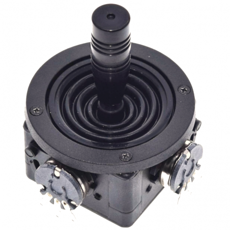

O Joystick JH-D202X-R2 / r4 5K é um joystick de painel que oferece uma aparência e acabamento agradável, bem como um controle de 2 eixos mais preciso do que é possível com um joystick de polegar padrão.
DESCRIÇÃO EM PORTUGUÊS BREVEMENTE DISPONÍVEL
Se tiver alguma dúvida neste produto não hesite em contactar-nos.
*Atenção: as imagens são meramente ilustrativas.
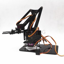
Typical applications include controlling remote motorized vehicles, motorized cameras, factory automation and electric wheelchairs.
The module includes two spring loaded 5K potentiometers that provide X and Y analog outputs which can be input to two analog inputs on an MCU.
The analog inputs on an MCU typical read values over a range of 0-1023 (for standard 10-bit ADC inputs like on most Arduino). The X-Axis and Y-Axis outputs from the Joystick should read around 512 (midpoint) when the control is at rest. As the joystick is moved, one or both of the outputs will register higher or lower values depending on how the control is being moved. When the joystick is released, it is spring-loaded and will return to center.
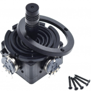
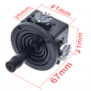
The joystick is designed to be panel mounted through a 41mm (1 5/8″) hole. The joystick is inserted from the bottom side of the panel. Four 2.5mm screws secure a pressure ring from the top side which locks the joystick in place.
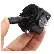
The shaft of the joystick extends through a rubber dust cover for a clean look and to provide some amount of protection against dust and moisture.
The two X/Y potentiometers have solder connections for wire hookup.
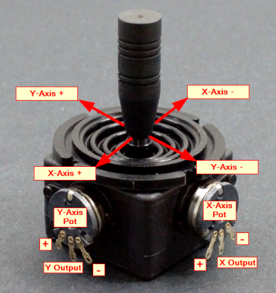
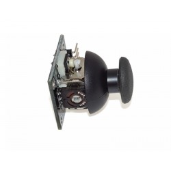
JH-D202X-R2_R4 Joystick 5K – Controls
Assigning which potentiometer is the X or Y is arbitrary and relative to the orientation of the joystick once it is mounted.
The labels in the picture just serve to provide on starting reference point.
When wiring the potentiometers, the center connection provides the output signal which represents the position of the joystick.
The two outside connections are typically hooked up to Vcc and ground to match the MCU. The + and – direction is relative to how the Vcc and grounds are connected to the potentiometers. These can be swapped if it is desired to swap the direction of the signal output as the joystick is moved.
These modules are quite useful for integrating into a final application such as for robotic control.
The program below illustrates and tests the basic functionality of the module. It reports the current state of the X-Axis and Y-Axis out to the Serial Monitor window.
The program uses analog pins A0 and A1, but these can be any 2 analog pins.
/*
JH-D202X-R2/R4 Joystick Module Test

Basic code for monitoring the outputs of the joystick.
*/
int xPin = A1;      // Use any analog input pin to read X-Axis pot
int yPin = A0;      // Use any analog input pin to read Y-Axis pot
int xPosition = 0;  // Variable to hold current X-Axis reading
int yPosition = 0;  // Variable to hold current Y-Axis reading
//===============================================================================
//  Initialization
//===============================================================================
void setup()
{
  Serial.begin(9600);
}
//===============================================================================
//  Main
//===============================================================================
void loop()
{
  xPosition = analogRead(xPin);         // Read the current state of both controls
  yPosition = analogRead(yPin);

  Serial.print("X: ");                  // Print state to Serial Monitor window
  Serial.print(xPosition);
  Serial.print(" | Y: ");
  Serial.println(yPosition);

  delay(250);    // add some delay between reads.
}
Notes:
| Operating Ratings | Vcc Range | 3.3 – 5V (typical) |
| Analog Outputs | 0 – Vcc | |
| Resistance Value | 5K ohm | |
| Resistance Tolerance | ± 20% | |
| Independent Linearity | ± 1% | |
| Restoration Error Rate | ≤ 30 ohms | |
| Joystick Stroke | ± 28 degrees | |
| Rated Life | 500,000 cycles | |
| Dimensions | Mounting Hole | 41mm (1 5/8″) |
| Mounting screw spacing | 32.5mm | |
| L x W x H | 49.6 x 49.6 x 66mm (1.95 x 1.95 x 2.60″) | |
Produtos Associados
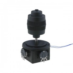

O Joystick JH-D202X-R2 / r4 5K é um joystick de painel que oferece uma aparência e acabamento agradável, bem como um controle de 2 eixos mais preciso do que é possível com um joystick de polegar padrão.