If you have any questions on this product please feel free to contact us.
*Disclaimer: The images are merely illustrative.
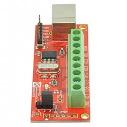
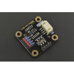
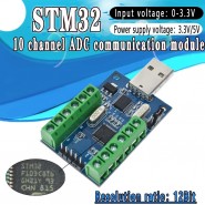
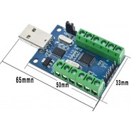
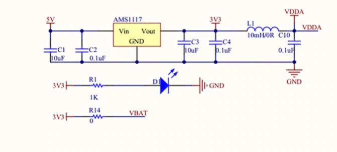
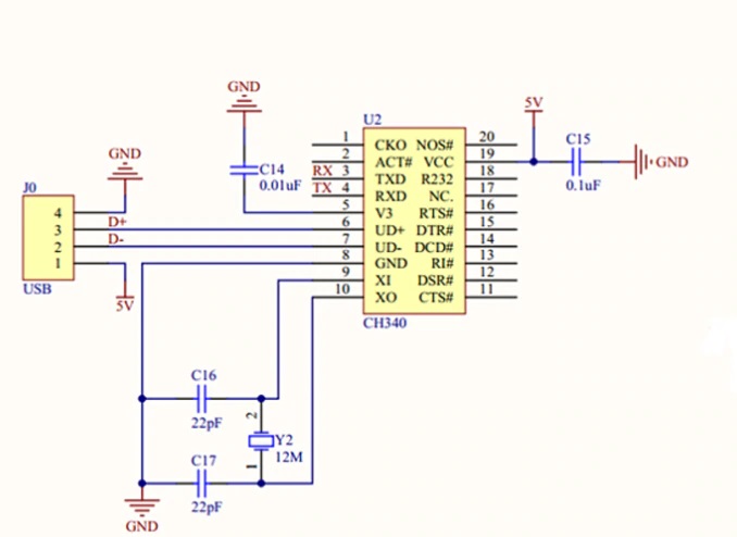
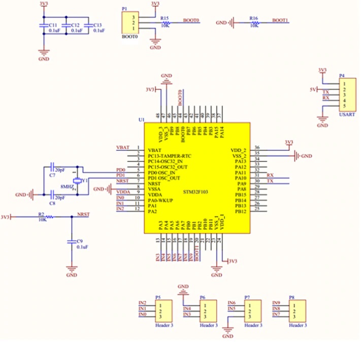
The 10-channel adc module uses the internal 10-channel adc features of the stm32f103 series as the sampling core, and transfers the acquired sampling data to the internal memory via the stm32 to reduce the cpu load and increase the sampling stability of the announcement. Accuracy, when the onboard usb to the serial port chip can transfer data to the host computer.
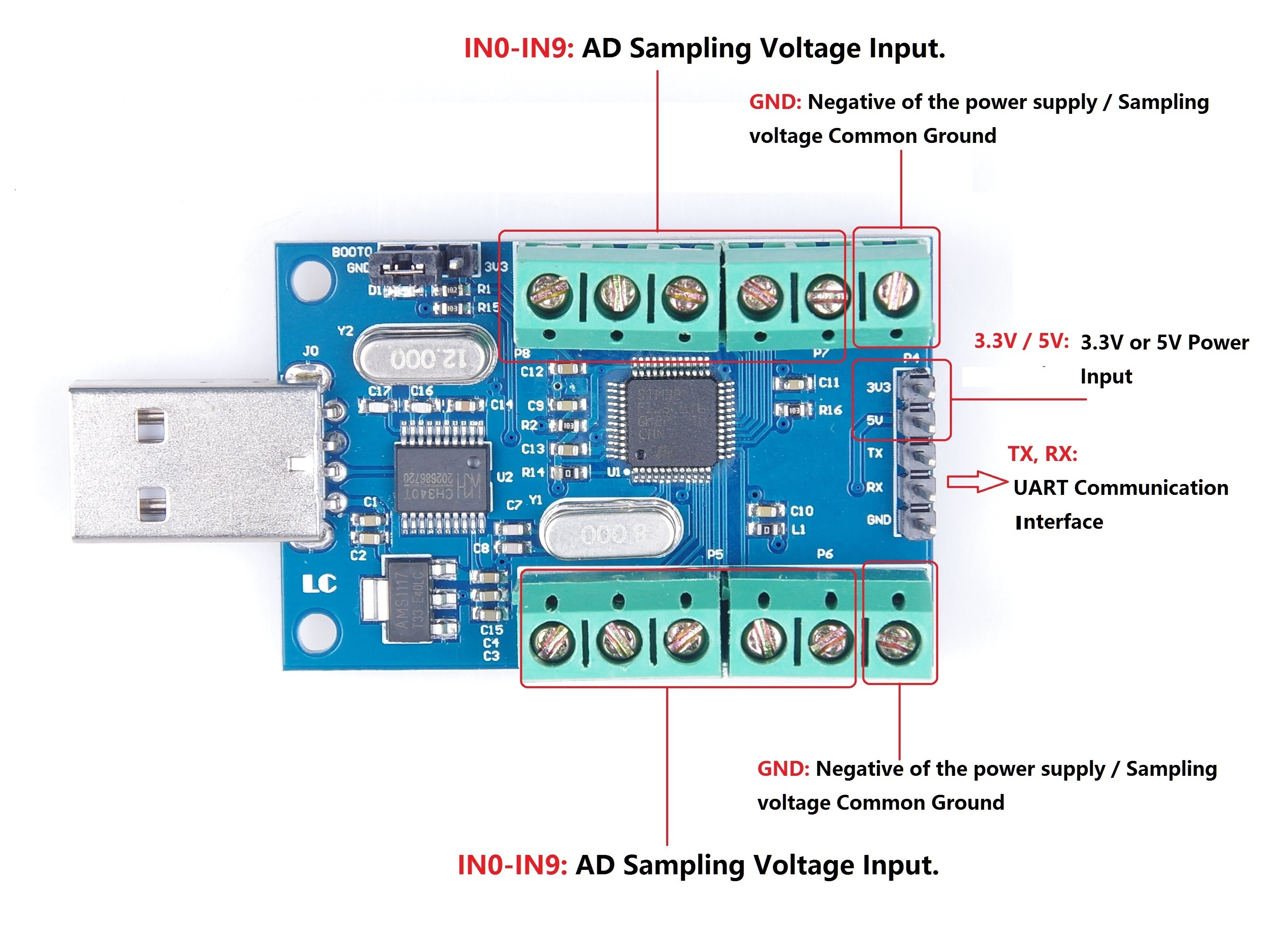
Install the usb to serial port chip ch340 driver, connect the module to the computer, IN0-IN9 is connected to the positive sampling voltage, gnd is connected to the negative sampling voltage (ie, common processing). Open the serial debugging wizard, select the port with correct and baud rate (115200). You can see the sampling result, it is updated once in 500ms. This time can modified on the source code.
If you want to use the external mcu to obtain the sampling data directly, you can connect the 3.3v, rx, tx, and gnd from the mcu to the 3.3v, tx, rx, and gnd of the module. Of course, it is ok to supply the module with 5v.
The data transfer protocol can be found by looking at the source code. If the customer wants to modify the source code, reprogram the program. The method is as follows: insert the module into the computer's usb port, insert the jumper plug into the module for the 3v3 end (note that it must be connected back to the gnd after programming is completed), open the flymcu programming software, open the hex file, set the port number and baud rate. For the relevant parameters, such as the special rate, click "start programming", then use the clamp to secure the two ends of the c9 capacitor (equivalent to reset).

Related products