Temperature sensor with relay output.
With a potenciometer defines the temperature and above this value the relay is triggered.
If you have any questions on this product please feel free to contact us.
*Disclaimer: The images are merely illustrative.
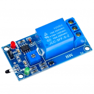
The Temperature Sensitive Relay Module 5V can automatically control a load such as a fan or heating device based on the temperature.
This is a self-contained switching module that energizes / de-energizes a relay based on the temperature. Just add 5V power and hook up the load you want to control then adjust the potentiometer to set the temperature at which you want the relay to switch between ON / OFF.
This type of module can be used for applications such as to automatically turn on an exhaust fan when the temperature gets above a preset level as might be the case in a green house or aquarium room or it could be used to energize a heating device when the temperature drops below a preset level.
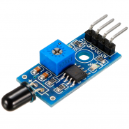
The temperature sensor on the module is a standard thermistor.
The temperature trip-point for triggering the relay can be adjusted using the potentiometer on the module. Turning the pot CW increases the temperature trip-point.
When the temperature goes over the trip-point value, an LM393 voltage comparator IC energizes the relay and it switches ON. A green LED is illuminated when the relay is energized.
When the temperature drops below the preset value, the relay switches back OFF.
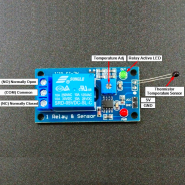
The relay has both NO (Normally Open) and NC (Normally Closed) contacts so the module can either be used to energize a load when temperature goes up past the trip-point value or when it goes down past that level.
A flyback diode is included on the module in parallel to the relay coil to safely shunt current when the relay coil is de-energized.
The module requires 5V power and ground to operate. There is a red LED that is lit when power is applied to the module. When the relay is energized, the module draws about 80mA from the Vcc pin.
1 x 2 Header (Power Connections)
The output of the relay is rated to switch up to 30VDC at 10A or up to 250VAC at up to 10A (See our notes below about the maximum VDC that can be switched).
The output is SPDT type with both a NO (Normally Open) terminal and a NC (Normally Closed) terminal relative to the COM terminal. When the relay is de-energized (green LED OFF) the NO-COM is open and the NC-COM is shorted. When the relay is energized (green LED ON) the NO – COM is shorted and the NC-COM is open.
1 x 3 Screw Terminal (Load Connections)
These are inexpensive modules that will work for a number of applications and allow you to control devices based on temperature without the need to have a uC involved. Just hook up 5V power and your load and you are all set.
We do find the DC rating of the relay to be too aggressive. With DC voltages above about 15V, the contacts can become a little sticky. We recommend using it to switch DC voltages of no more than 15V.
With AC, the relays performed very well in our testing. To test the upper limit we used it to switch a 1500W heater that draws about 12.5A and the relay handled it without any problems though you should not exceed 10A in normal use.
To test the device, connect it to power and adjust the pot so that the green LED just goes out. Warming the thermistor should cause the green LED to come on and an audible click heard from the relay as it switches.
To adjust the pot for the final application will take a little trial and error since the module uses a relative adjustment rather than being able to set it to a specific temperature level. There is also quite a bit of hysteresis in the switching. If you are trying to maintain a particular temperature with a level of precision, check out our W1209 and W1219 temperature controller modules below which may offer better value for your application.
If the module has long leads on the thermistor, ensure the leads stay separated and do not touch each other or the sensor will not work.
Notes:
| Vcc | Typical | 5V |
| Contact Rating | DC | 15V @ 10A (Tested to 15V @ 6A) |
| 115VAC | 10A | |
| 250VAC | 10A | |
| Module Size | L x W x H (PCB) | 50 x 27 x 18mm (2 x 1.1 x 0 .71″) |
| Hole pattern | 44.5 x 20.5mm (1.75 x 0.80″) | |
| Hole size | M3 |

Related products

Temperature sensor with relay output.
With a potenciometer defines the temperature and above this value the relay is triggered.