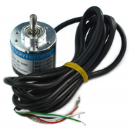
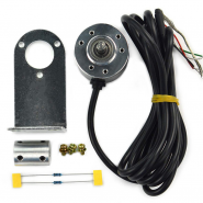
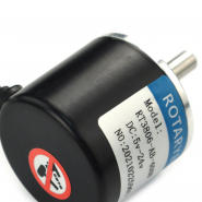
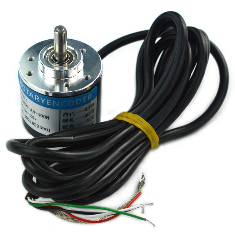
This is an industrial incremental photoelectric rotary encoder with aluminum material, metal shell and stainless steel shaft. It generates AB two-phase orthogonal pulse signal though the rotation of the grating disk and optocoupler.
If you have any questions on this product please feel free to contact us.
*Disclaimer: The images are merely illustrative.
DESCRIÇÃO EM PORTUGUÊS BREVEMENTE DISPONÍVEL
Se tiver alguma dúvida neste produto não hesite em contactar-nos.
*Atenção: as imagens são meramente ilustrativas.

This is an industrial incremental photoelectric rotary encoder with aluminum material, metal shell and stainless steel shaft. It generates AB two-phase orthogonal pulse signal though the rotation of the grating disk and optocoupler. 400 pulses/round for each phase, and 1600 pulses/round for dual-phase 4 times output. This rotary encoder supports max 5000 r/min speed. And it can be used for speed, angle, angular velocity and other data measurement. The photoelectric rotary encoder has a NPN open collector output. It could work with Microcontroller with internal pull-up resistors directly. And it is using 750L05 voltage regulator chip, which has a DC4.8V-24V wide range power input, compatible with Arduino, STM32, PLC and other types of microcontrollers.

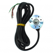
| Num | Label | Description |
|---|---|---|
| Red | VCC | Power + |
| Black | GND | Power - |
| White | A | Pulse A (Need pull-up Resistor) |
| Green | B | Pulse B (Need pull-up Resistor) |
Direction & Interrupt count
Hardware
Software

/*!
 * @file  SEN0230.ino
 * @brief  Two phase quadrature encoder(Incremental)
 * @n  To determine motor with encode (CW OR CCW)
 * @copyright  Copyright (c) 2010 DFRobot Co.Ltd (http://www.dfrobot.com)
 * @license  The MIT License (MIT)
 * @author  Dongzi(1185787528@qq.com)
 * @version  V1.0
 * @date  2016-5-26
 */

#define  A_PHASE 2
#define  B_PHASE 3
unsigned int flagA = 0;  //Assign a value to the token bit
unsigned int flagB = 0;  //Assign a value to the token bit
/** *  */
void setup() {
  pinMode(A_PHASE, INPUT);
  pinMode(B_PHASE, INPUT);
  Serial.begin(9600);   //Serial Port Baudrate: 9600
  attachInterrupt(digitalPinToInterrupt( A_PHASE), interrupt, RISING); //Interrupt trigger mode: RISING
}
void loop() {

  Serial.print("CCW:  ");
  Serial.println(flagA);
  Serial.print("CW: ");
  Serial.println(flagB);
  delay(1000);// Direction judgement

}
void interrupt()// Interrupt function
{ char i;
  i = digitalRead( B_PHASE);
  if (i == 1)
    flagA += 1;
  else
    flagB += 1;
}
Use the interruption to detect the rotation direction and count cylinder number.


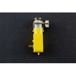
Related products
This is an industrial incremental photoelectric rotary encoder with aluminum material, metal shell and stainless steel shaft. It generates AB two-phase orthogonal pulse signal though the rotation of the grating disk and optocoupler.