
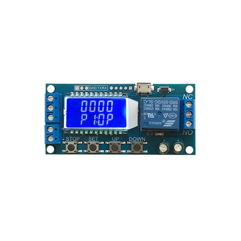
This product as a lcd display, very clear, simple and easy to use, powerful, but please read user instructions carefully before using.
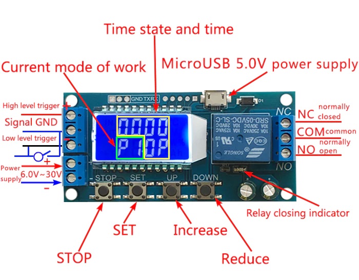
Display shows 4 parameters:
If you have any questions on this product please feel free to contact us.
*Disclaimer: The images are merely illustrative.
Relay module with 7 operation modes.
Timing Range: 0.01 sec~9999 min
This product as a lcd display, very clear, simple and easy to use, powerful, but please read user instructions carefully before using.
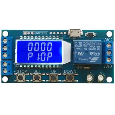
1. Display shows 4 parameters:
2. Trigger mode: high and low level.
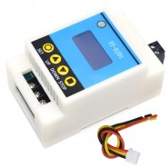
3. Power supply: 6~30V, also supports micro USB 5.0V, very convenient.
4. Parameters can be modified via UART.
5. Stop button to provide emergency stop function.
6. 5 minutes without any operation the borad goes into low-power state. Any action trigger the wake up.
7. OP/CL/LP params can be modified individually
8. All parameters are automatically saved by power off.
P1 ( Timer ON ): After trigger signal, relay is ON during OP time then disconnects; During OP time a new trigger signal as no function.
P2 ( Timer ON with restart ): After trigger signal, relay is ON during OP time then disconnects; During OP time a new trigger signal restart the timer. (This is a good function to implement a WatchDog timer)
P3 ( Timer ON with reset ): After trigger signal, relay is ON during OP time then disconnects; During OP time a new trigger signal resets the timer and disconnect the relay.
P4 ( Delay to ON ): After trigger signal, relay remains OFF during CL time then close the relay and start the OP time. After OP time the relay disconnects. A new trigger with time running reset the timer and disconnect the relay.
P5 ( Loop with reset ): Same as P4 but looping with LP number of cycles and relay starts ON. A new trigger with time running, resets the timer loop and disconnects the relay. With this function you can make a square wave with LP number of cycles or loops forever if LP is ----.
P6 ( Run on POWER ON ): On POWER ON system loops with LP number of cycles. A new trigger with time running as no function.
P7 ( Signal hold function ): If the trigger signal is maintained, the time remains cleared and the relay is ON. When the trigger signal disappears, the relay disconnects after the OP time. During OP time a new trigger signal resets the timer and disconnect the relay.
1. Power Supply: 6V~30V and micro USB 5.0 V
2. Trigger signal source: High level(3.0V~24.0V),Low level(0.0V ~0.2V),Switch signal.
3. Maximum Output load: DC 30V 5A and AC 220V 5A.
4. Static Current: 15mA Operating current: 50mA.
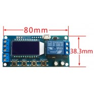
5. Working temperature: -40-85°C; size: 8.0x3.8x1.9cm.
6. Optocoupler isolation, Strong anti-interference ability, Industrial grade circuit board.
In the OP/CL parameter modification interface, press the STOP button shortly to select the timing range.
XXXX Timer range: 1sec~9999sec
XXX.X Timer range: 0.1sec~999.9sec
XX.XX Timer range: 0.01sec~99.99sec
X.X.X.X Timer range: 1min~999.9min
For example, if you want to set the OP to 3.2 seconds, move the decimal point to ten digits. LCD display 003.2
Parameter Description: OP on-time, CL off time, LP cycle times (1 - 9999 times, "----" represents an infinite number of cycles)
a) Press and hold the SET key to enter the setting interface;
b) First set the working mode, work mode flashes reminder, set the working mode by pressing the UP / DOWN keys;
c) Short press the SET button to select the working mode and enter the system parameter settings.
d) In the system parameter setting interface, press SET key to switch the system parameters to be modified, and press / long press UP/DOWN key to modify. (Note: Short press SET in P-1~P-3, P-7 mode is invalid);
e) In the OP/CL parameter modification interface, short press STOP to switch the timer unit (1s/0.1s/0.01s/1min);
f) After all parameters are set, press and hold the SET button for more than 2 seconds to release the hand, save the parameter settings and exit the setting interface
The system supports UART parameter reading and writing functions;
UART:9600,8,1
|
CMD |
Function |
|
read |
Read system parameters |
|
OP:xxxx OP:xxx.x OP:xx.xx OP:x.x.x.x |
1s 0.1s 0.01s 1 min |
|
CL:xxxx CL:xxx.x CL:xx.xx CL:x.x.x.x |
1s 0.1s 0.01s 1 min |
|
LP:xxxx |
Settings Cycles |
|
on |
Relay enable |
|
off |
Relay disable |
|
PX |
Set the working mode (P1~P7) |
a) Low-power state: In the running interface, by pressing the STOP button for a long time, the Low-power function is started or closed (L-P selects on to start the hibernation function, and off turns off the hibernation function);
b) Relay function selection: In the operation interface, by pressing the STOP button shortly, the relay function is started or closed, 'on' meets the conduction condition relay normally turns on, 'OFF' meets the conduction condition relay does not turn on; 'OFF' In the state, the system flashes 'OUT';
c) Parameter view: In the operation interface, short press the SET key to display the current parameter setting of the system, without affecting the normal operation of the system;
d) Display content switching: In P-5 P-6 mode, switch display content (run time/cycle number) by pressing DOWN key momentarily;

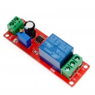
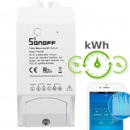
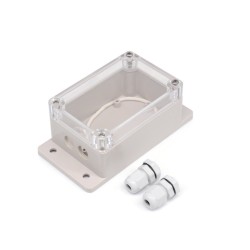
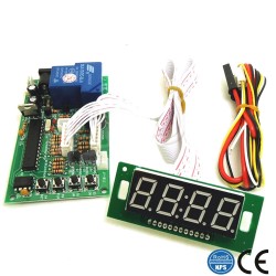
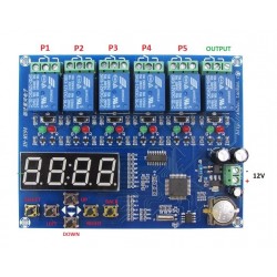
Related products
This product as a lcd display, very clear, simple and easy to use, powerful, but please read user instructions carefully before using.
Display shows 4 parameters: