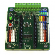
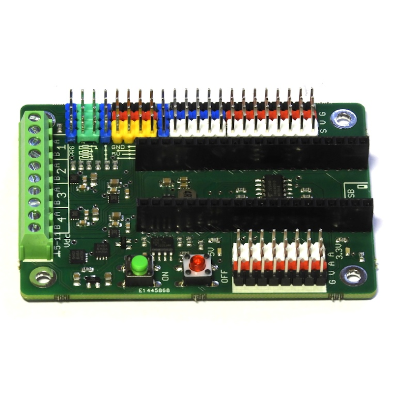
The PICO4DRIVE is a development board designed to handle small robotics projects. It supports up to 4 DC brushed motors with up to 2 Amps each (4A peak) or other devices that require high currents, like solenoids. With its 5V switching power supply, it can also provide power to 5V devices. Since the Pico inputs are not 5V tolerant, the board includes two resistor divider networks that allowconnecting two 5V signals safely to the Pico (or up to 12V).
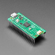
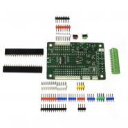
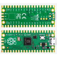
NOTE: This board is not soldered yet. At the bottom of the page, you have the assembly instructions. Raspberry Pi Pico not included.
If you have any questions on this product please feel free to contact us.
*Disclaimer: The images are merely illustrative.
4x full bridge drivers, up to 2A continuous / 4A peak each, with short-circuit / over-current protection
8x analog inputs via analog multiplexer
13x GPIO pins accessible on headers
5V, 1.5A switching power supply
On board AVR tiny micro-controller providing
ON/OFF control with push-buttons
battery voltage monitoring and reporting
allows Pico software to turn off the board
auto power off on battery low condition
ON button can be used as a user application button
over-voltage protection up to 25V
Reverse polarity protection
Flexible header configuration:
directly plug up to 4 servo motor connectors
resistor divider network to scale down inputs above 3.3V
Input voltage range: 5V ... 11V
Dimension: 77x55mm
NOTE: This board is not soldered yet. At the bottom of the page, you have the assembly instructions.
The PICO4DRIVE is a development board designed to handle small robotics projects. It supports up to 4 DC brushed motors with up to 2 Amps each (4A peak) or other devices that require high currents, like solenoids. With its 5V switching power supply, it can also provide power to 5V devices. Since the Pico inputs are not 5V tolerant, the board includes two resistor divider networks that allowconnecting two 5V signals safely to the Pico (or up to 12V).
The board includes an AVR tiny micro-controller to monitor and control the power supply to the board. When off, the AVR tiny is in sleep mode so that the board consumes a total of 3uA. Pressing the ON button wakes the AVR and allows it to check the input voltage and decide if it should turn the circuit on or not. This way the AVR can provide under and over voltage protection, power off when the battery voltage is low (protecting the battery from being completely depleted), allow the software on the Pico to request to power off (e.g., to implement an inactivity timeout) and even use the ON button as an application button, by sending button press information to the Pico.
The board also solves the Pico’s limitation of having just 3 analog inputs by using an analog multiplexer and one Pico input to provide 8 analog inputs, giving a total of 10 analog inputs (2 direct, 8 multiplexed).
The GPIO’s that are used internally for the motor drivers, analog multiplexer or communicating with the AVR micro-controller (a single pin) are not present in the header pins. All 13 GPIO’s available on the headers are simply directly connected to the Pico board and are not used for other functions on the pico4drive board at all.
The board headers provide flexible connections to handle different usage scenarios. Some examples
include:
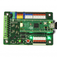
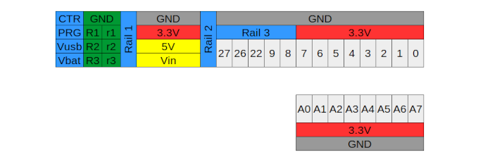
Rail 3 can be connected to Rail 1 using a jumper and Rail 2 can be connected to either 5V or Vin using another jumper. With this configuration, servo motors can be directly connected to the columns of GPIO’s 8, 9, 22, 25 using standard (GND, PWR, PULSE) servo connectors.
If Rail 3 is not going to be used to drive servo motors and more 3.3V pins are needed, a single jumper connecting the 3.3V on the column of GPIO 7 to Rail 3 on GPIO8 will provide 3 extra 3.3V pins. Alternatively, if the Rail 3 pins are not needed as power supply pins, Rail 3 can be used as just another rail to connect the same signal to multiple endpoints, like the other rails.
The resistor divider pins are set up so that connecting a signal between 0 and 5V on pin R2 will scale it to a signal between 0 and 3.3V on pin R1. Alternatively, connecting a 12V signal on R3 will also scale it down to 3.3V on R1. On the diagram above, (R1,R2,R3) is one divider and (r1,r2,r3) is the other divider. For more details, consult the schematic document (at the bottom of the page).
For simple projects, that don’t require a lot of current, the Vusb and Vbat pins on the leftmost column can be connected with a jumper (like is shown in the photo above).
Note that doing this will connect Vbat to the USB power supply directly, so the Vbat input on the terminal block can not be connected to a different power source. Also, all the current will pass through the Pico’sUSB connector, so it’s not recommended to draw more than 500mA from the power supply.
The GPIO headers have two pins to allow for either sending an output signal to two different devices, or to make it easy to connect an oscilloscope probe to any GPIO or analog input, ofr debugging purposes.
The under-voltage protection implemented on the factory default AVR tiny firmware is calibrated to handle 2LiPo cells in series. The firmware supports 5V inputs but to avoid triggering the under-voltage protection, a special power-on sequence is required: press and hold OFF, press ON, release OFF. After selecting this mode, the board will keep the battery under-voltage protection disabled
until the input voltage is removed.
Find Github Pico4Driver Library here

Related products
The PICO4DRIVE is a development board designed to handle small robotics projects. It supports up to 4 DC brushed motors with up to 2 Amps each (4A peak) or other devices that require high currents, like solenoids. With its 5V switching power supply, it can also provide power to 5V devices. Since the Pico inputs are not 5V tolerant, the board includes two resistor divider networks that allowconnecting two 5V signals safely to the Pico (or up to 12V).
NOTE: This board is not soldered yet. At the bottom of the page, you have the assembly instructions. Raspberry Pi Pico not included.