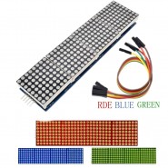


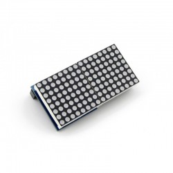
This LED matrix requires only three IO ports from the microcontroller to drive the matrix with no flicker! You could connect multiple matrix in cascade!
On the following link you can find an Arduino Tutorial:
https://www.makerguides.com/max7219-led-dot-matrix-display-arduino-tutorial/
If you have any questions on this product please feel free to contact us.
*Disclaimer: The images are merely illustrative.
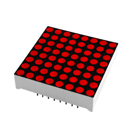
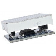
This matrix as one MAX7219 chip with with serial input/output common-cathode display drivers that interface microprocessors (µPs) to 7-segment numeric LED displays of up to 8 digits, bar-graph displays, or 64 individual LEDs. Included on-chip are a BCD code-B decoder, multiplex scan circuitry, segment and digit drivers, and an 8x8 static RAM that stores each digit. Only one external resistor is required to set the segment current for all LEDs.
A convenient 4-wire serial interface connects to all common µPs. Individual digits may be addressed and updated without rewriting the entire display.
The devices include a 150µA low-power shutdown mode, analog and digital brightness control, a scan-limit register that allows the user to display from 1 to 8 digits, and a test mode that forces all LEDs on.
This Matrix requires only three IO ports from the microcontroller to drive the matrix with no flicker!
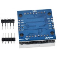
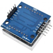
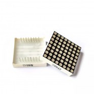
1. The left side of the module as an input port, an output port on the right.
2. You can use it as a single module matrix, in this case simply connect input port to CPU
3. Cascading multiple modules, CPU -> 1st module input and output 1st module -> 2nd module input... and so on
4. 8051 Microcontroller connection example:
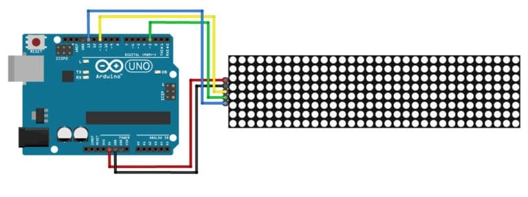
5. Arduino conection example:
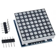
1. 1x MAX7219 dot matrix module
2. 2x 5 Pin Header (for soldering)

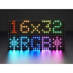
Related products

This LED matrix requires only three IO ports from the microcontroller to drive the matrix with no flicker! You could connect multiple matrix in cascade!
On the following link you can find an Arduino Tutorial:
https://www.makerguides.com/max7219-led-dot-matrix-display-arduino-tutorial/