If you have any questions on this product please feel free to contact us.
*Disclaimer: The images are merely illustrative.
Introduction:
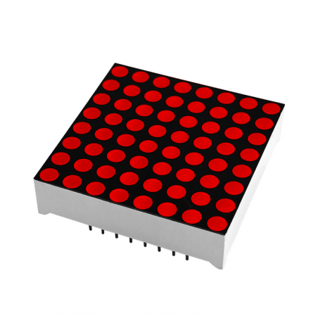
This matrix as one MAX7219 chip with with serial input/output common-cathode display drivers that interface microprocessors (µPs) to 7-segment numeric LED displays of up to 8 digits, bar-graph displays, or 64 individual LEDs. Included on-chip are a BCD code-B decoder, multiplex scan circuitry, segment and digit drivers, and an 8x8 static RAM that stores each digit. Only one external resistor is required to set the segment current for all LEDs.
A convenient 4-wire serial interface connects to all common µPs. Individual digits may be addressed and updated without rewriting the entire display.
The devices include a 150µA low-power shutdown mode, analog and digital brightness control, a scan-limit register that allows the user to display from 1 to 8 digits, and a test mode that forces all LEDs on.
This Matrix requires only three IO ports from the microcontroller to drive the matrix with no flicker!
Parameters:
- 10MHz Serial Interface
- Individual LED Segment Control
- Decode/No-Decode Digit Selection
- 150µA Low-Power Shutdown (Data Retained)
- Digital and Analog Brightness Control
- Display Blanked on Power-Up
- Drive Common-Cathode LED Display
- 5V working voltage
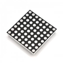
- A single MAX7219 chip can drive a total of 8x8 dot matrix
- Size (4xMatrix): 3.2 cm*3.2 cm *1.3 cm (L*W*H)
- With fixing screw holes (3mm diameter)
Wiring instructions:
1. The left side of the module as an input port, an output port on the right.
2. You can use it as a single module matrix, in this case simply connect input port to CPU
3. Cascading multiple modules, CPU -> 1st module input and output 1st module -> 2nd module input... and so on
4. 8051 Microcontroller connection example:
- VCC → 5V
- GND → GND
- DIN → P2.2
- CS → P2.1
- CLK → P2.0
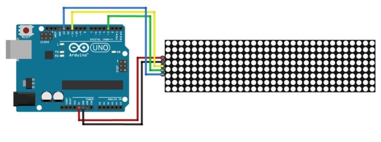
5. Arduino conection example:
Shipping list:
1. 1x MAX7219 dot matrix module
2. 2x 5 Pin Header (for soldering)
