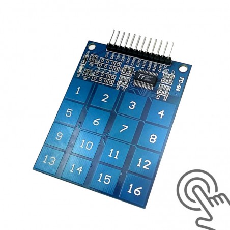

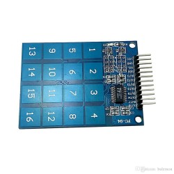
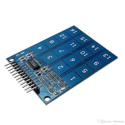
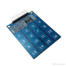
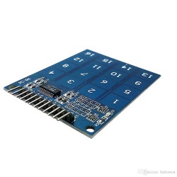

This capacitive touch sensor module uses the TTP229 integrated circuit, making it easy to add capacitive touch input to your project. It features 16 sensitive touch pads that make an ideal replacement for the old fashioned keypads.
If you have any questions on this product please feel free to contact us.
*Disclaimer: The images are merely illustrative.
This capacitive touch sensor module uses the TTP229 integrated circuit, making it easy to add capacitive touch input to your project. It features 16 sensitive touch pads that make an ideal replacement for the old fashioned keypads.
TTP229-Capacitive-Touch-Sensor-Module-16-channels-Datasheet

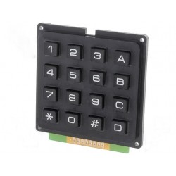
Related products
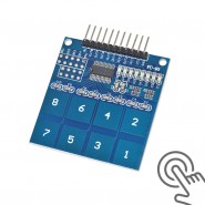

This capacitive touch sensor module uses the TTP229 integrated circuit, making it easy to add capacitive touch input to your project. It features 16 sensitive touch pads that make an ideal replacement for the old fashioned keypads.