
- New
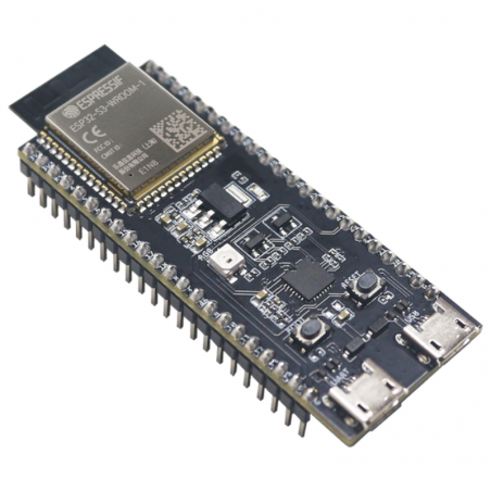

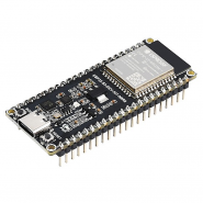
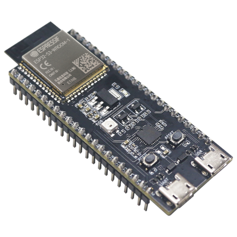
The ESP32-S3-DevKitC-1 is an entry-level development board equipped with ESP32-S3-WROOM-1, ESP32-S3-WROOM-1U, or ESP32-S3-WROOM-2, a general-purpose Wi-Fi + Bluetooth® Low Energy MCU module that integrates complete Wi-Fi and Bluetooth Low Energy functions.
If you have any questions on this product please feel free to contact us.
*Disclaimer: The images are merely illustrative.
Wi-Fi 802.11 b/g/n and Bluetooth® 5.x (BLE) connectivity
Based on the ESP32-S3-WROOM-1-N8R8 module with 8 MB Flash and 8 MB SRAM
Compatible with rapid prototyping and breadboard assembly
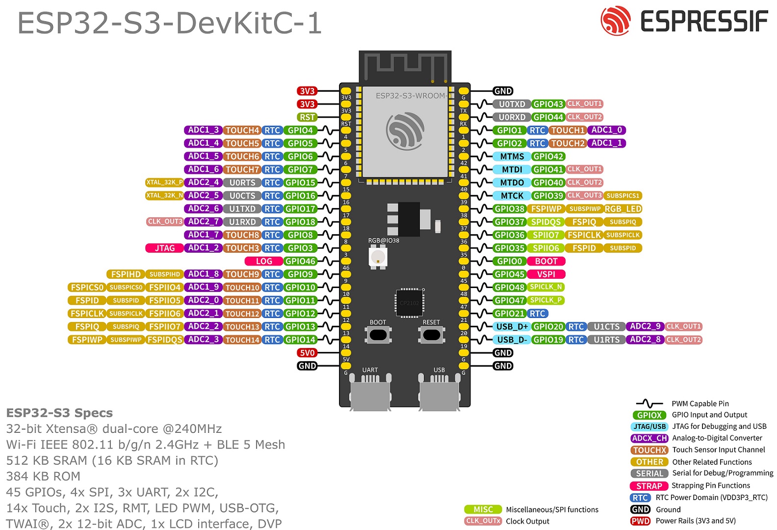
Supports ADC, GPIO, I2C, I2S, PWM, SPI, UART, and USB interfaces
Integrated addressable RGB LED and 3.3V power LED
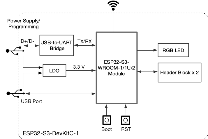
Powered via USB port, 5V/GND pins, or 3V3/GND pins
Boot and reset buttons
Integrated USB-UART converter for programming and debugging
Wireless:
Wi-Fi + Bluetooth Low Energy (BLE)
Operating Frequency: 2.4 GHz
Memory:
8 MB Flash (Quad SPI)
8 MB RAM (Octal SPI)
Available Interfaces:
ADC
GPIO
I2C
I2S
PWM
SPI
UART
USB 1.1 (OTG and UART)
Power Supply:
5V DC via USB port or pins
Internal conversion to 3.3V via LDO
Connectors:
Pin header
Micro-USB port
Dimensions: 62.74 × 25.4 mm
Weight: 53.19 g
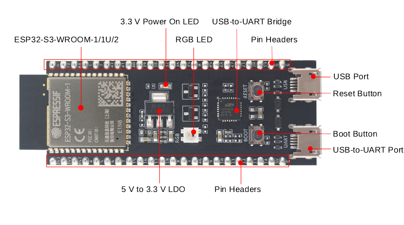
The key components of the board are described in a counter-clockwise direction.
|
Key Component |
Description |
|---|---|
|
ESP32-S3-WROOM-1/1U/2 |
ESP32-S3-WROOM-1, ESP32-S3-WROOM-1U, and ESP32-S3-WROOM-2 are powerful, generic Wi-Fi + Bluetooth Low Energy MCU modules that have a rich set of peripherals. They provide acceleration for neural network computing and signal processing workloads. ESP32-S3-WROOM-1 and ESP32-S3-WROOM-2 comes with a PCB antenna. ESP32-S3-WROOM-1U comes with an external antenna connector. |
|
5 V to 3.3 V LDO |
Power regulator that converts a 5 V supply into a 3.3 V output. |
|
Pin Headers |
All available GPIO pins (except for the SPI bus for flash) are broken out to the pin headers on the board for easy interfacing and programming. For details, please see Header Block. |
|
USB-to-UART Port |
A Micro-USB port used for power supply to the board, for flashing applications to the chip, as well as for communication with the chip via the on-board USB-to-UART bridge. |
|
Boot Button |
Download button. Holding down Boot and then pressing Reset initiates Firmware Download mode for downloading firmware through the serial port. |
|
Reset Button |
Press this button to restart the system. |
|
USB Port |
ESP32-S3 full-speed USB OTG interface, compliant with the USB 1.1 specification. The interface is used for power supply to the board, for flashing applications to the chip, for communication with the chip using USB 1.1 protocols, as well as for JTAG debugging. |
|
USB-to-UART Bridge |
Single USB-to-UART bridge chip provides transfer rates up to 3 Mbps. |
|
RGB LED |
Addressable RGB LED, driven by GPIO38. |
|
3.3 V Power On LED |
Turns on when the USB power is connected to the board. |

Related products
The ESP32-S3-DevKitC-1 is an entry-level development board equipped with ESP32-S3-WROOM-1, ESP32-S3-WROOM-1U, or ESP32-S3-WROOM-2, a general-purpose Wi-Fi + Bluetooth® Low Energy MCU module that integrates complete Wi-Fi and Bluetooth Low Energy functions.
