- DISCONTINUED


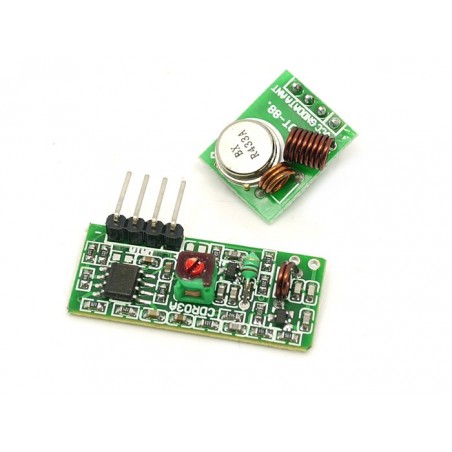
433Mhz RF link kit
If you have any questions on this product please feel free to contact us.
*Disclaimer: The images are merely illustrative.
Description:
The kit is consisted of transmitter and receiver, popular used for remote control.
Basic Specification:
Usage:
The popular link is like this: MCU -> Encoder -> Transmitter ------ Receiver -> Decoder -> MCU,
PT2272(Encoder) and PT2262(Decoder) are optional, their existence is to 1)avoid confusing when multiple RF links in range 2) isolate disturbance. You can integrate the encoding and decoding work to the MCUs on both side. Whenever there is no 315Mhz devices around, you may use it as direct cable connection.
Excuse for the documentation, we will work on them. Before that, please consult us for any details, we are happy to find the answer for you. We tried them using the guide from Sparkfun, it's compatible. The only difference is in package, of some excess GND pins.
Moreover, we will make more RF modules ourselves with different frequency and capacity. The next one in plan is based on cc1100 Please suggest us about your need .
Documents
Please visit our wiki page for more info about this product. It will be appreciated if you can help us improve the documents, add more demo code or tutorials. For technical support, please post your questions to our forum.
/*

  Example for receiving


  https://github.com/sui77/rc-switch/


  If you want to visualize a telegram copy the raw data and

  paste it into http://test.sui.li/oszi/

*/
#include
RCSwitch mySwitch = RCSwitch();
void setup() {

  Serial.begin(9600);

  mySwitch.enableReceive(0);  // Receiver on interrupt 0 => that is pin #2

}
void loop() {

  if (mySwitch.available()) {

    output(mySwitch.getReceivedValue(), mySwitch.getReceivedBitlength(), mySwitch.getReceivedDelay(), mySwitch.getReceivedRawdata(),mySwitch.getReceivedProtocol());

    mySwitch.resetAvailable();

  }

}
/*

  Example for different sending methods


  https://github.com/sui77/rc-switch/


*/
#include
RCSwitch mySwitch = RCSwitch();
void setup() {
  Serial.begin(9600);


  // Transmitter is connected to Arduino Pin #10

  mySwitch.enableTransmit(10);


  //Optional set protocol (default is 1, will work for most outlets)

  mySwitch.setProtocol(1);
  //Optional set pulse length.

  mySwitch.setPulseLength(320);


  //Optional set number of transmission repetitions.

     mySwitch.setRepeatTransmit(5);


}
void loop() {
  /* See Example: TypeA_WithDIPSwitches */

  mySwitch.switchOn("11111", "00010");

  delay(1000);

  mySwitch.switchOff("11111", "00010");

  delay(1000);
  /* Same switch as above, but using decimal code */

  mySwitch.send(5393, 24);

  delay(1000);

  mySwitch.send(5396, 24);

  delay(1000);
  /* Same switch as above, but using binary code */

  mySwitch.send("000000000001010100010001");

  delay(1000);

  mySwitch.send("000000000001010100010100");

  delay(1000);
  /* Same switch as above, but tri-state code */

  mySwitch.sendTriState("00000FFF0F0F");

  delay(1000);

  mySwitch.sendTriState("00000FFF0FF0");

  delay(1000);
  delay(20000);

}

433Mhz RF link kit
